
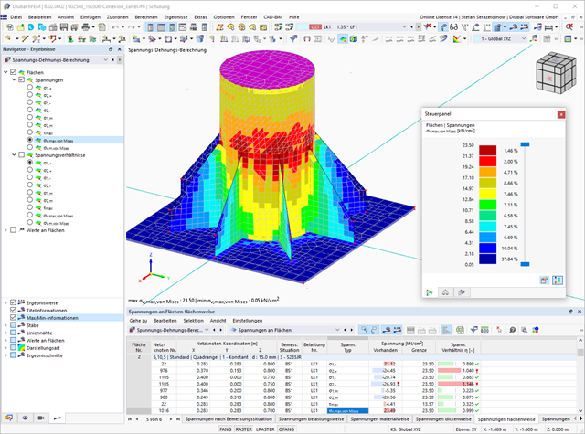
As soon as the program has completed the calculation, the summary of the results is listed. All result windows are integrated in the main program RFEM/RSTAB. You will find all the results arranged in tables; they can be displayed for each individual time step or as an envelope, and you also have the option of displaying the results graphically as well as animating them.
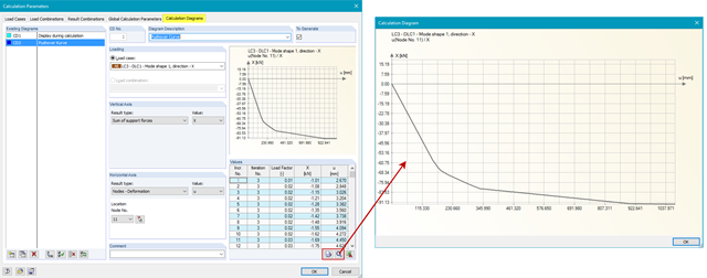
The results from the time history analysis can be displayed in the calculation diagrams. All the results are shown as a function of time. You can export the numeric values to MS Excel.
All result tables and graphics are part of the RFEM/RSTAB printout report. In this way, you can ensure clearly arranged documentation. You can also export the tables to MS Excel.
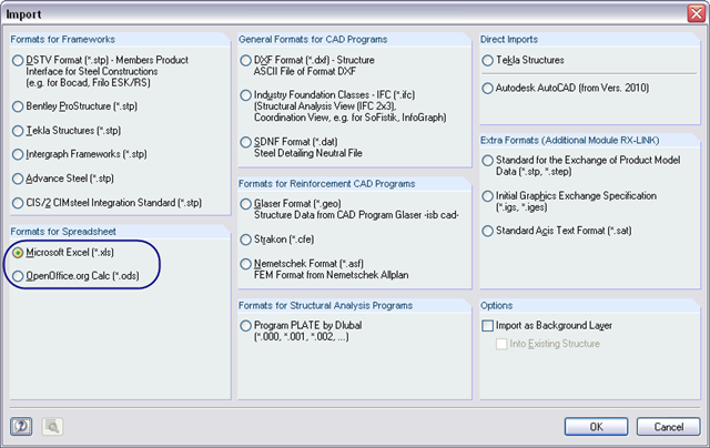
You can import table values from a prepared Excel table into RFEM 6 / RSTAB 9 with just a few clicks – either individually or all at once. For the import, you need to install a plug-in in Microsoft Excel according to this FAQ.
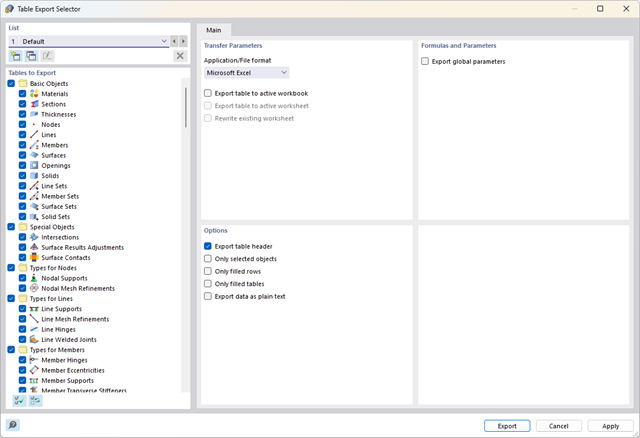
Did you know? You can export all RFEM/RSTAB tables with the results individually or all at once directly into an Excel table or as a CSV file. There are several options available to you:
- With table headers
- Selected objects only
- Filled rows only
- Only filled tables
- Export data as plain text
This way, the program allows you to control and clearly manage the exported data. You can export the stored formulas directly in the table or as a separate table, as in the case of the used parameters.
.jpg?mw=640&hash=26a7c7d3eca4bc6f129e08b373eac4f2314109ba)
Take your structural design one step further. RFEM 6 and RSTAB 9 support now a new file format for structural design, Structural Analysis Format (SAF). For this, both programs allow for the import as well as the export. SAF is a file format based on MS Excel, intended to facilitate the exchange of structural analysis models between different software applications.

As soon as the program has completed the calculation, the eigenvalues, natural frequencies and periods are listed. These result windows are integrated in the main program RFEM/RSTAB. You can find all mode shapes of the structure in tables and also have an option to display them graphically and to animate them.
All result tables and graphics are part of the RFEM/RSTAB printout report. In this way, you can ensure clearly arranged documentation. You can also export the tables to MS Excel.
- Extensive library of rolled, parametric thin-walled and thick-walled cross-sections
- Extensible library for material properties
- Import of dxf files
- Cross-section properties of thin-walled or thick-walled cross-sections
- Ideal section properties of cross-sections consisting of different materials
- Stress analysis
- Plastic capacity design with interaction of internal forces according to the Simplex Method
- Design of reinforcement and the subsequent design of concrete cross-section in the Concrete Design add-on (see Product Feature)
- Saving cross-sections as a block
- Scripting with JavaScript
- Interface with MS Excel for exporting tables
- Connection to Webservice & API (for example, optional creation of cross-section and access to result tables)
- Printout report
Did you know? When unloading the structural component with a plastic material model, in contrast to the Isotropic | Nonlinear Elastic material model, the strain remains after it has been completely unloaded.
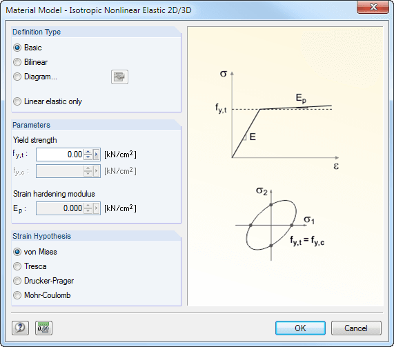
You can select three different definition types:
- Standard (definition of the equivalent stress under which the material plastifies)
- Bilinear (definition of the equivalent stress and strain hardening modulus)
- Stress-strain diagram: definition of polygonal stress-strain diagram
- Option to save / import the diagram
- Interface with MS Excel
If you release a structural component with a nonlinear elastic material again, the strain goes back on the same path. In contrast to the Isotropic|Plastic material model, there is no strain left when completely unloaded.
You can select three different definition types:
- Standard (definition of the equivalent stress under which the material plastifies)
- Bilinear (definition of the equivalent stress and strain hardening modulus)
- Stress-Strain Diagram:
- Definition of polygonal stress-strain diagram
- Option to save / import the diagram
- Interface with MS Excel
Background information about nonlinear material models can be found in the technical article describing the yield laws in isotropic nonlinear elastic material model.
The RF-MOVE/RSMOVE add-on module does not display any result windows: You can check the created load cases, including loads, in RFEM/RSTAB. Descriptions of the individual moving loads are created on the basis of the respective load increment number.
However, it is possible to modify the descriptions in RFEM/RSTAB. You can export all data in tables to MS Excel.
In RFEM, it is possible to determine pushover curves (also called capacity curves) and export them to Excel.
With the RF-DYNAM Pro - Equivalent Loads add-on module, it is possible to generate load distribution automatically in accordance with a mode shape and export it as a load case to RFEM.
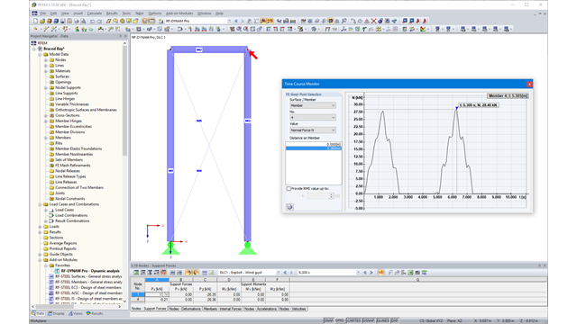
Due to the integration of RF‑/DYNAM Pro in RFEM or RSTAB, you can incorporate numeric and graphic results from RF‑/DYNAM Pro - Nonlinear Time History to the global printout report. Also, all RFEM and RSTAB options are available for a graphical visualization. The results of the time history analysis are displayed in a time history diagram.
The results are displayed as a function of time and the numerical values can be exported to MS Excel. Result combinations can be exported, either as a result of a single time step or the most unfavorable results of all time steps are filtered out.
- Design of the following roof types:
- Monopitch roof
- Duopitch Roof
- Curved roof
- All roof shapes allow for a free selection of stiffening diagonals. The following types are available:
- Falling diagonals
- Rising diagonals
- Crossing diagonals with verticals
- Crossing diagonals without verticals
- Crossing diagonals with steel strips (ties)
- Consideration of window rows in the ridge by selecting an inner intermediate part.
- For design according to EC 5 (EN 1995), the following National Annexes are available:
-
 DIN EN 1995-1-1/NA:2013-08 (Germany)
 -
 NBN EN 1995-1-1/ANB:2012-07 (Belgium)
 -
 DK EN 1995-1-1/NA:2011-12 (Denmark)
 -
 SFS EN 1995-1-1/NA:2007-11 (Finland)
 -
 NF EN 1995-1-1/NA:2010-05 (France)
 -
 UNI EN 1995-1-1/NA:2010-09 (Italy)
 -
 NEN EN 1995-1-1/NB:2007-11 (Netherlands)
 -
 ÖNORM B 1995-1-1:2015-06 (Austria)
 -
 PN EN 1995-1-1/NA:2010-09 (Poland)
 -
 SS EN 1995-1-1 (Sweden)
 -
 STN EN 1995-1-1/NA:2008-12 (Slovakia)
 -
 SIST EN 1995-1-1/A101:2006-03 (Slovenia)
 -
 CSN EN 1995-1-1:2007-09 (Czech Republic)
 -
 BS EN 1995-1-1/NA:2009-10 (the United Kingdom)
-
- Simple geometry input with illustrative graphics
- Automatic generation of wind loads
- Automatic creation of required combinations for the ultimate and serviceability limit states, as well as fire resistance design
- Free definition of the load cases to be used
- Extensive material library
- Optional extension of material library by further materials
- Extensive library of permanent loads
- Allocation of framework to service classes and specification of service class categories
- Determination of design ratios, support forces, and deformations
- Info icon indicating successful or failed design
- Color reference scales in result tables
- Direct data export to MS Excel
- DXF interface for preparation production documents in CAD
- Program languages: English, German, Czech, Italian, Spanish, French, Portuguese, Polish, Chinese, Dutch, and Russian
- Verifiable printout report, including all required designs. Printout report available in many output languages; for example, English, German, French, Italian, Spanish, Russian, Czech, Polish, Portuguese, Chinese, and Dutch.
- In the ultimate limit state design, the stiffness of the hinge is divided by the partial safety factor and in the serviceability limit state design calculated using the mean stiffnesses. The limit values for the ultimate and the serviceability limit states can be defined separately.
- Design of the following geometrical types:
- Single-span beams with and without cantilevers
- Continuous beams with and without cantilevers
- Hinged girder system (Gerber beams) with and without cantilevers
- Automatic generation of wind and snow loads
- Automatic creation of required combinations for the ultimate and serviceability limit states, as well as fire resistance design
- For design according to EC 5 (EN 1995), the following National Annexes are available:
-
DIN EN 1995-1-1/NA:2013-08 (Germany)
-
NBN EN 1995-1-1/ANB:2012-07 (Belgium)
-
DK EN 1995-1-1/NA:2011-12 (Denmark)
-
SFS EN 1995-1-1/NA:2007-11 (Finland)
-
NF EN 1995-1-1/NA:2010-05 (France)
-
UNI EN 1995-1-1/NA:2010-09 (Italy)
-
NEN EN 1995-1-1/NB:2007-11 (Netherlands)
-
ÖNORM B 1995-1-1:2015-06 (Austria)
-
PN EN 1995-1-1/NA:2010-09 (Poland)
-
SS EN 1995-1-1 (Sweden)
-
STN EN 1995-1-1/NA:2008-12 (Slovakia)
-
SIST EN 1995-1-1/A101:2006-03 (Slovenia)
-
CSN EN 1995-1-1:2007-09 (Czech Republic)
-
BS EN 1995-1-1/NA:2009-10 (the United Kingdom)
-
- Consideration of optimization options by user specifications according to the respective standard:
- Shear force reduction of single loads near support
- Shear force reduction of load introduction at the cross-section top point
- Moment redistribution in support zone
- Reduction of torsional stress by means of user-defined entry of moment
- Increase of bending stiffnesses for flat-ended or edgewise bending strains
- Simple geometry input with illustrative graphics
- Extensive material library for both standards
- Optional extension of material library by further materials
- Extensive library of permanent loads
- Allocation of framework to service classes and specification of service class categories
- Determination of design ratios, support forces, and deformations
- Info icon indicating successful or failed design
- Color reference scales in result tables
- Direct data export to MS Excel
- Program languages: English, German, Czech, Italian, Spanish, French, Portuguese, Polish, Chinese, Dutch, and Russian
- Verifiable printout report, including all required designs. Printout report available in many output languages; for example, English, German, French, Italian, Spanish, Russian, Czech, Polish, Portuguese, Chinese, and Dutch.
- Direct import of stp files from various CAD programs
- Design of the following column types:
- Hinged column, optionally with elastic restraint of head or footing
- Bracket, optionally with elastic restraint of footing
- Simple geometry input with illustrative graphics
- Extensive material library
- Allocation of framework to service classes and specification of service class categories
- Detailed settings of the fire resistance design
- Specification of limit deformation for the serviceability limit state design
- Determination of design ratios, support forces, and deformations
- For design according to EC 5 (EN 1995), the following National Annexes are available:
-
DIN EN 1995-1-1/NA:2013-08 (Germany)
-
NBN EN 1995-1-1/ANB:2012-07 (Belgium)
-
DK EN 1995-1-1/NA:2011-12 (Denmark)
-
SFS EN 1995-1-1/NA:2007-11 (Finland)
-
NF EN 1995-1-1/NA:2010-05 (France)
-
UNI EN 1995-1-1/NA:2010-09 (Italy)
-
NEN EN 1995-1-1/NB:2007-11 (Netherlands)
-
ÖNORM B 1995-1-1:2015-06 (Austria)
-
PN EN 1995-1-1/NA:2010-09 (Poland)
-
SS EN 1995-1-1 (Sweden)
-
STN EN 1995-1-1/NA:2008-12 (Slovakia)
-
SIST EN 1995-1-1/A101:2006-03 (Slovenia)
-
CSN EN 1995-1-1:2007-09 (Czech Republic)
-
BS EN 1995-1-1/NA:2009-10 (the United Kingdom)
- Automatic generation of wind and snow loads
- Multiple optional reductions according to the selected standard
- Direct data export to MS Excel
- Program languages: English, German, Czech, Italian, Spanish, French, Portuguese, Polish, Chinese, Dutch, and Russian
- Verifiable printout report, including all required designs. Printout report available in many output languages; for example, English, German, French, Italian, Spanish, Russian, Czech, Polish, Portuguese, Chinese, and Dutch.
- Direct import of stp files from various CAD programs
- Design of the following geometrical types:
- Single-span beams with and without cantilevers
- Continuous beams with and without cantilevers
- Hinged girder system (Gerber beams) with and without cantilevers
- For design according to EC 5 (EN 1995), the following National Annexes are available:
-
DIN EN 1995-1-1/NA:2013-08 (Germany)
-
NBN EN 1995-1-1/ANB:2012-07 (Belgium)
-
DK EN 1995-1-1/NA:2011-12 (Denmark)
-
SFS EN 1995-1-1/NA:2007-11 (Finland)
-
NF EN 1995-1-1/NA:2010-05 (France)
-
UNI EN 1995-1-1/NA:2010-09 (Italy)
-
NEN EN 1995-1-1/NB:2007-11 (Netherlands)
-
ÖNORM B 1995-1-1:2015-06 (Austria)
-
PN EN 1995-1-1/NA:2010-09 (Poland)
-
SS EN 1995-1-1 (Sweden)
-
STN EN 1995-1-1/NA:2008-12 (Slovakia)
-
SIST EN 1995-1-1/A101:2006-03 (Slovenia)
-
CSN EN 1995-1-1:2007-09 (Czech Republic)
-
BS EN 1995-1-1/NA:2009-10 (the United Kingdom)
-
- Automatic generation of wind and snow loads
- Multiple optional reductions according to the selected standard
- Simple geometry input with illustrative graphics
- Free entry of tapered geometries. Free selection of the grain angle allows for user-defined design of the compressive and tensile areas for bending
- Comprehensive and extensible material library
- Determination of design ratios, support forces, and deformations
- Color reference scales in result tables
- Direct data export to MS Excel
- DXF interface for preparation production documents in CAD
- Program languages: English, German, Czech, Italian, Spanish, French, Portuguese, Polish, Chinese, Dutch, and Russian
- Verifiable printout report, including all required designs. Printout report available in many output languages; for example, English, German, French, Italian, Spanish, Russian, Czech, Polish, Portuguese, Chinese, and Dutch.
- Direct import of stp files from various CAD programs

- Import of materials, cross-sections, and internal forces from RFEM/RSTAB
- Steel design of thin‑walled cross‑sections according to EN 1993‑1‑1:2005 and EN 1993‑1‑5:2006
- Automatic classification of cross-sections according to EN 1993-1-1:2005 + AC:2009, Cl. 5.5.2, and EN 1993-1-5:2006, Cl. 4.4 (cross-section class 4), with optional determination of effective widths according to Annex E for stresses under fy
- Integration of parameters for the following National Annexes:
-
DIN EN 1993-1-1/NA:2015-08 (Germany)
-
ÖNORM B 1993-1-1:2007-02 (Austria)
-
NBN EN 1993-1-1/ANB:2010-12 (Belgium)
-
 BDS EN 1993-1-1/NA:2008 (Bulgaria)
 -
DS/EN 1993-1-1 DK NA:2015 (Denmark)
-
SFS EN 1993-1-1/NA:2005 (Finland)
-
NF EN 1993-1-1/NA:2007-05 (France)
-
 ELOT EN 1993-1-1 (Greece)
 -
UNI EN 1993-1-1/NA:2008 (Italy)
-
 LST EN 1993-1-1/NA:2009-04 (Lithuania)
 -
 UNI EN 1993-1-1/NA:2011-02 (Italy)
 -
 MS EN 1993-1-1/NA:2010 (Malaysia)
 -
NEN EN 1993-1-1/NA:2011-12 (Netherlands)
- NS EN 1993-1-1/NA:2008-02 (Norway)
-
PN EN 1993-1-1/NA:2006-06 (Poland)
-
 NP EN 1993-1-1/NA:2010-03 (Portugal)
 -
 SR EN 1993-1-1/NB:2008-04 (Romania)
 -
SS EN 1993-1-1/NA:2011-04 (Sweden)
-
 SS EN 1993-1-1/NA:2010 (Singapore)
 -
STN EN 1993-1-1/NA:2007-12 (Slovakia)
-
SIST EN 1993-1-1/A101:2006-03 (Slovenia)
-
 UNE EN 1993-1-1/NA:2013-02 (Spain)
 -
CSN EN 1993-1-1/NA:2007-05 (Czech Republic)
-
BS EN 1993-1-1/NA:2008-12 (the United Kingdom)
-
 CYS EN 1993-1-1/NA:2009-03 (Cyprus)
 - In addition to the National Annexes (NA) listed above, you can also define a specific NA, applying user‑defined limit values and parameters.
- Automatic calculation of all required factors for the design value of flexural buckling resistance Nb,Rd
- Automatic determination of the ideal elastic critical moment Mcr for each member or set of members on every x-location according to the Eigenvalue Method or by comparing moment diagrams. You only have to define the lateral intermediate supports.
- Design of tapered members, unsymmetric sections or sets of members according to the General Method as described in EN 1993-1-1, Cl. 6.3.4
- In the case of the General Method according to Cl. 6.3.4, optional application of "European lateral-torsional buckling curve" according to Naumes, Strohmann, Ungermann, Sedlacek (Stahlbau 77 [2008], pp. 748‑761)
- Rotational restraints can be taken into account (trapezoidal sheeting and purlins)
- Optional consideration of shear panels (for example, trapezoidal sheeting and bracing)
- RF-/STEEL Warping Torsion module extension (license required) for stability analysis according to the second-order analysis as stress analysis including consideration of the 7th degree of freedom (warping)
- Module extension RF-/STEEL Plasticity (license required) for plastic analysis of cross‑sections according to Partial Internal Forces Method (PIFM) and Simplex Method for general cross‑sections (in connection with the RF‑/STEEL Warping Torsion module extension, it is possible to perform the plastic design according to the second‑order analysis)
- Module extension RF-/STEEL Cold-Formed Sections (license required) for ultimate and serviceability limit state designs for cold-formed steel members according to the EN 1993-1-3 and EN 1993-1-5 standards
- ULS design: Selection of fundamental or accidental design situations for each load case, load combination, or result combination
- SLS design: Selection of characteristic, frequent, or quasi-permanent design situations for each load case, load combination, or result combination
- Tension analysis with definable net cross-section areas for member start and end
- Weld designs of welded cross-sections
- Optional calculation of warp spring for nodal support on sets of members
- Graphic of design ratios on cross-section and in RFEM/RSTAB model
- Determination of governing internal forces
- Filter options for graphical results in RFEM/RSTAB
- Representation of design ratios and cross‑section classes in the rendered view
- Color scales in result windows
- Automatic cross-section optimization
- Transfer of optimized cross-sections to RFEM/RSTAB
- Parts lists and quantity surveying
- Direct data export to MS Excel
- Verifiable printout report
- Possibility to include the temperature curve in the report
.png?mw=640&hash=688fdfc8af4828c08e9851cddb103a1e86cb899a)
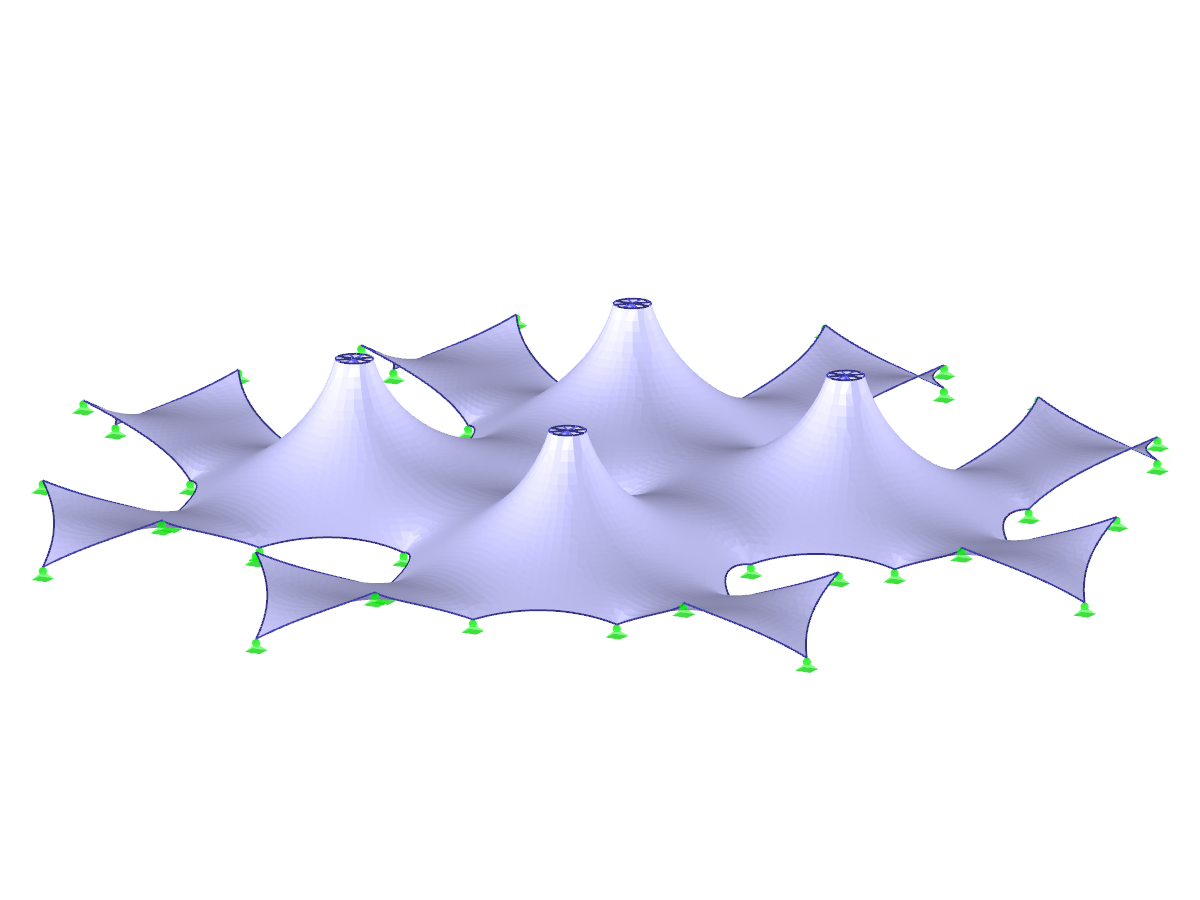
- Form-finding of:
- tension-loaded membrane and cable structures
- compression-loaded shell and beam structures
- mixed tension- and compression-loaded structures
- Consideration of gas chambers between surfaces
- Interaction with supporting structure (substructure design according to various standards)
- Surfaces as a 2D and members as a 1D element
- Definition of different prestress conditions for surfaces (membranes and shells)
- Definition of forces or geometrical requirements for members (cables and beams)
- Consideration of individual loads (self‑weight, inner pressure, and so on) in the form‑finding process
- Temporary support definitions for the form-finding process
- Automatic preliminary form-finding of membrane surfaces (more information...)
- Definition of isotropic or orthotropic material for structural analysis
- Optional definition of free polygon loads
- Transformation of form‑found shape elements into NURBS surface elements
- Possibility of combined form-finding by integration of preliminary form-finding
- Graphical evaluation of the new form using colored coordinates and inclination plots
- Complete documentation of the calculation including user-defined adaptive evaluation figures
- Optional export of the FE mesh as a DXF or Excel file
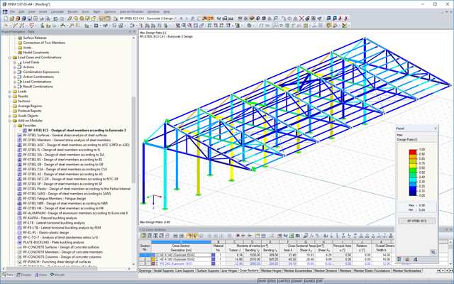
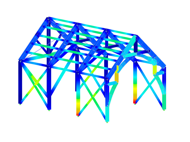
The results sorted by load case, cross-section, member, set of members, or x-location are displayed in clearly arranged result windows. By selecting the corresponding table row, detailed information about the performed design is displayed.
The results include a comprehensible list of all material and cross-section properties, design internal forces, and design factors. Furthermore, it is possible to display the distribution of internal forces of each x-location in a separate graphic window.
Parts lists by members/sets of members for the individual cross-section types complete the detailed and structured display of results. To print input data and results, you can use the global printout report in RFEM/RSTAB.
For further processing of various data, it is possible to export all tables to MS Excel.

- Modeling of the cross-section via elements, sections, arcs, and point elements
- Expansible library of material properties, yield strengths, and limit stresses
- Section properties of open, closed, or non-connected cross-sections
- Ideal section properties of cross-sections consisting of different materials
- Determination of weld stresses in fillet welds
- Stress analysis including design of primary and secondary torsion
- Check of c/t-ratios
- Effective cross-sections according to
- EN 1993-1-5 (including stiffened buckling panels according to Section 4.5)
-
 EN 1993-1-3
 -
EN 1999-1-1
-
to DIN 18800-2
- Classification according to
-
EN 1993-1-1
-
EN 1999-1-1
-
- Interface with MS Excel to import and export tables
- Printout report
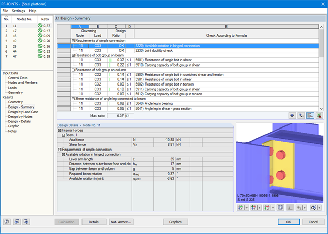
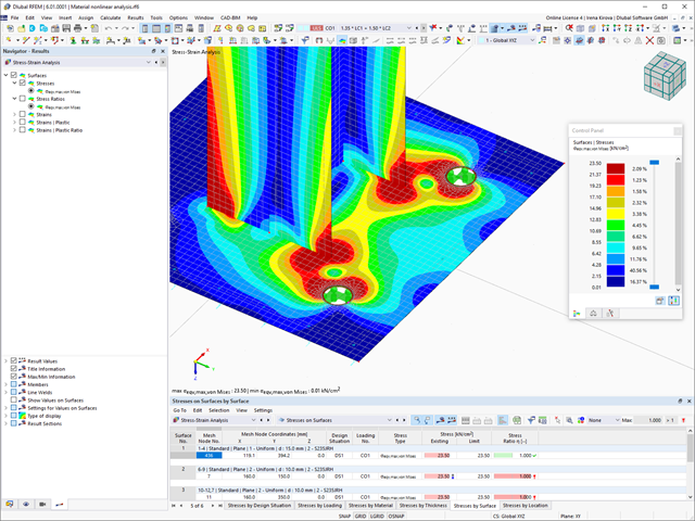
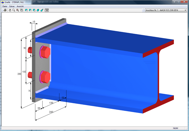
The result windows list all results of the calculation in detail. In addition, 3D graphics are created, where individual components as well as dimension lines and, for example, This allows you, for example, to display or hide the weld data. The summary shows if the individual designs have been fulfilled: The design ratio is additionally visualized with a green data bar, which turns red when the design is not fulfilled. Furthermore, the node number and the governing LC/CO/RC are displayed.
When selecting a design, the module shows the detailed intermediate results including the actions and the additional internal forces from the connection geometry. There is the option to display the results by load case and by node. The connections are represented in a realistic 3D rendering possible to scale. In addition to the main views, it is possible to show the graphics from any perspective.
You can add the graphics with dimensions and labels to the RFEM/RSTAB printout or export them as DXF. The printout report includes all input and result data prepared for test engineers. It is possible to export all tables to MS Excel or in a CSV file. A special transfer menu defines all specifications required for the export.
All design results and design checks are displayed in detail and in a comprehensible manner. An error log indicates non-designable situations or failed recommendations. Due to the permanent integration in RFEM/RSTAB, subsequent modifications in the structural system and in loading are automatically taken into account for the connections to be checked.
If one of the designs could not be fulfilled, the corresponding line is highlighted in red. The output appears in a short or a long form in the global printout report of RFEM/RSTAB. Furthermore, you can easily export all result tables to MS Excel or in a CSV file. A special transfer menu defines all specifications required for the export.
The following material models are available in RF − MAT NL:
Isotropic Plastic 1D/2D/3D and Isotropic Nonlinear Elastic 1D/2D/3D
You can select three different definition types here:
- Basic (definition of the equivalent stress under which the material plastifies)
- Bilinear (definition of the equivalent stress and strain hardening modulus)
- Diagram:
- Definition of polygonal stress-strain diagram
- Option to save / import the diagram
- Interface with MS Excel
Orthotropic Plastic 2D/3D (Tsai-Wu 2D/3D)
This material model allows the definition of material properties (modulus of elasticity, shear modulus, Poisson's ratio) and ultimate strengths (tension, compression, shear) in two or three axes.
Isotropic Masonry 2D
It is possible to specify the limit tension stresses σx,limit and σy,limit as well as the hardening factor CH.
Orthotropic Masonry 2D
The material model Orthotropic Masonry 2D is an elastoplastic model that additionally allows softening of the material, which can be different in the local x- and y-directions of a surface. The material model is suitable for (unreinforced) masonry walls with in-plane loads.
Isotropic Damage 2D/3D
Here, you can define antimetric stress-strain diagrams. The modulus of elasticity is calculated in each step of the stress-strain diagram using Ei = (σi -σi-1 )/(εi -εi-1 ).
- Full integration in RFEM/RSTAB including import of all relevant information and internal forces
- For design according to EN 1995-1-1, the following National Annexes are available:
-
DIN EN 1995-1-1/NA:2013-08 (Germany)
-
ÖNORM B 1995-1-1:2015-06 (Austria)
-
NBN EN 1995-1-1/ANB:2012-07 (Belgium)
-
BDS EN 1995-1-1/NA:2012-02 (Bulgaria)
-
DK EN 1995-1-1/NA:2011-12 (Denmark)
-
SFS EN 1995-1-1/NA:2007-11 (Finland)
-
NF EN 1995-1-1/NA:2010-05 (France)
-
 I S. EN 1995-1-1/NA:2010-03 (Ireland)
 -
UNI EN 1995-1-1/NA:2010-09 (Italy)
-
 LVS EN 1995-1-1/NA:2012-05 (Latvia)
 -
LST EN 1995-1-1/NA:2011-10 (Lithuania)
-
LU EN 1995-1-1/NA:2011-09 (Luxembourg)
-
NEN EN 1995-1-1/NB:2007-11 (Netherlands)
-
 NS EN 1995-1-1/NA:2010-05 (Norway)
 -
PN EN 1995-1-1/NA:2010-09 (Poland)
-
NP EN 1995-1-1 (Portugal)
-
SR EN 1995-1-1/NB:2008-03 (Romania)
-
SS EN 1995-1-1 (Sweden)
-
STN EN 1995-1-1/NA:2008-12 (Slovakia)
-
SIST EN 1995-1-1/A101:2006-3 (Slovenia)
-
UNE EN 1995-1-1/AN:2016-04 (Spain)
-
CSN EN 1995-1-1/NA:2007-09 (Czech Republic)
-
BS EN 1995-1-1/NA:2009-10 (the United Kingdom)
-
CYS EN 1995-1-1/NA:2011-02 (Cyprus)
-
- Extensive material library in compliance with the EN, SIA, and DIN standards
- Design of circular, rectangular, and user-defined composite cross-sections (also hybrids)
- Specific classification of a structure in service classes (SECL) and actions in load duration classes (LDC)
- Design of members and sets of members
- Stability analysis according to the Equivalent Member Method or the second-order analysis
- Determination of governing internal forces
- Icon providing information about successful or failed design
- Visualization of the design criterion on RFEM/RSTAB model
- Automatic cross-section optimization
- Parts lists and quantity surveying
- Data export to MS Excel
- Free configuration of charring time and charring rates, as well as free choice of charring sides for fire design
- Fire resistance designs in the selected standard according to:
-
 EN 1995-1-2
 -
SIA 265:2012 + SIA 265-C1:2012
-
to DIN 4102-22:2004
-
- Import of buckling lengths from the RF-STABILITY/RSBUCK add-on module
- Design of tapered members according to the previously defined cut-to-grain angle
- Ridge design and analysis of transversal tension stresses for defined ridges
- Design of curved members and sets of members
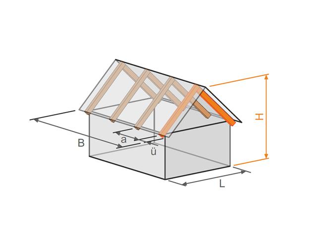
- Design of the following roof types:
- Flat Roof
- Monopitch roof
- Duopitch roof (symmetrical/asymmetrical)
- Definition of any additional support and free selection of degrees of freedom (additional free definition of translational and rotational spring stiffness of supports and hinges)
- Arrangement of up to five collar/tie beams, including intermediate support for duopitch roof
- Automatic generation of wind and snow loads
- Automatic generation of required combinations for the ultimate and serviceability limit states, as well as fire resistance design (additional definition of several member and nodal loads)
- For design according to EC 5 (EN 1995), the following National Annexes are available:
-
Germany DIN EN 1995-1-1/NA:2013-08 (Germany)
-
NBN EN 1995-1-1/ANB:2012-07 (Belgium)
-
BDS EN 1995-1-1/NA:2012-02 (Bulgaria)
-
DK EN 1995-1-1/NA:2011-12 (Denmark)
-
SFS EN 1995-1-1/NA:2007-11 (Finland)
-
NF EN 1995-1-1/NA:2010-05 (France)
-
I S. EN 1995-1-1/NA:2010-03 (Ireland)
-
UNI EN 1995-1-1/NA:2010-09 (Italy)
-
NEN EN 1995-1-1/NB:2007-11 (Netherlands)
-
ÖNORM B 1995-1-1:2015-06 (Austria)
-
PN EN 1995-1-1/NA:2010-09 (Poland)
-
SS EN 1995-1-1 (Sweden)
-
STN EN 1995-1-1/NA:2008-12 (Slovakia)
-
SIST EN 1995-1-1/A101:2006-03 (Slovenia)
-
CSN EN 1995-1-1:2007-09 (Czech Republic)
-
BS EN 1995-1-1/NA:2009-10 (the United Kingdom)
-
CYS EN 1995-1-1/NA:2011-02 (Cyprus)
-
- Simple geometry input with illustrative graphics
- Input of tapered cantilevers with cut-to-grain on the bottom side of rafters
- Extensive material library that can be extended by user-defined materials
- Determination of design ratios, support forces, and deformations
- Color reference scales in result tables
- Direct data export to MS Excel
- Program languages: English, German, Czech, Italian, Spanish, French, Portuguese, Polish, Chinese, Dutch, and Russian
- Verifiable printout report, including all required designs. Printout report available in many output languages; for example, English, German, French, Italian, Spanish, Russian, Czech, Polish, Portuguese, Chinese, and Dutch.
- Full integration in RFEM/RSTAB including import of all relevant information and internal forces
- Design of members and continuous members for tension, compression, bending, shear, and combined internal forces
- Stability analysis for lateral-torsional buckling and buckling according to the equivalent member method or the second order analysis
- Serviceability limit state design by limitation of deflections
- Free configuration of charring time and charring rates, as well as free choice of charring sides for fire design
- South African material library and cross‑section library
- User-defined entry of rectangular and circular cross-sections
- Cross-section optimization with optional transfer to RFEM/RSTAB
- Optional import of effective lengths from the RSBUCK or RF‑STABILITY add‑on module
- Detailed result documentation including references to design equations of the used standard
- Various filter and sorting options of results including result lists by member, cross-sections, x-location, or by load case, load and result combination
- Consideration of moisture service conditions
- Visualization of the design criterion on the RFEM/RSTAB model
- Data export to MS Excel
- Design of members and continuous members for tension, compression, bending, shear, and combined internal forces
- Stability analysis for lateral-torsional buckling and buckling according to the equivalent member method or the second order analysis
- Serviceability limit state design by limitation of deflections
- Free configuration of charring time and charring rates, as well as free choice of charring sides for fire design
- Design of tapered and curved beams consisting of glulam timber
- Material and cross‑section library based on the Canadian standard
- User-defined entry of rectangular and circular cross-sections
- Automatic cross-section optimization
- Optional import of buckling lengths from the RF-STABILITY/RSBUCK module
- Detailed result documentation including references to design equations of the used standard
- Various filtering and sorting options of results
- Consideration of moisture service conditions
- Visualization of design criterion on RFEM/RSTAB model
- Data export to MS Excel
- Units metric and imperial
- Design of the following geometrical types:
- Symmetrical / asymmetrical
- Half-frame
- Column sloping inside / outside
- Intermediate piece with / without
- Direction of lamellas can be defined as parallel to inner or outer edge
- For design according to EC 5 (EN 1995), the following National Annexes are available:
-
DIN EN 1995-1-1/NA:2013-08 (Germany)
-
NBN EN 1995-1-1/ANB:2012-07 (Belgium)
-
DK EN 1995-1-1/NA:2011-12 (Denmark)
-
SFS EN 1995-1-1/NA:2007-11 (Finland)
-
NF EN 1995-1-1/NA:2010-05 (France)
-
UNI EN 1995-1-1/NA:2010-09 (Italy)
-
NEN EN 1995-1-1/NB:2007-11 (Netherlands)
-
ÖNORM B 1995-1-1:2015-06 (Austria)
-
PN EN 1995-1-1/NA:2010-09 (Poland)
-
SS EN 1995-1-1 (Sweden)
-
STN EN 1995-1-1/NA:2008-12 (Slovakia)
-
SIST EN 1995-1-1/A101:2006-03 (Slovenia)
-
CSN EN 1995-1-1:2007-09 (Czech Republic)
-
BS EN 1995-1-1/NA:2009-10 (the United Kingdom)
-
- Simple geometry input with illustrative graphics
- Automatic generation of wind and snow loads
- Automatic creation of required combinations for the ultimate and serviceability limit states, as well as fire resistance design
- Possibility to define load cases and load applications
- Extensive material library for both standards
- Optional extension of material library by further materials
- Extensive library of permanent loads
- Allocation of framework to service classes and specification of service class categories
- Determination of design ratios, support forces, and deformations
- Info icon indicating successful or failed design
- Color reference scales in result tables
- Direct data export to MS Excel
- DXF interface for preparation production documents in CAD
- Program languages: English, German, Czech, Italian, Spanish, French, Portuguese, Polish, Chinese, Dutch, and Russian
- Verifiable printout report, including all required designs. Printout report available in many output languages; for example, English, German, French, Italian, Spanish, Russian, Czech, Polish, Portuguese, Chinese, and Dutch.
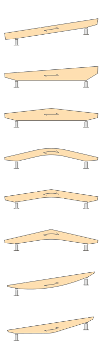
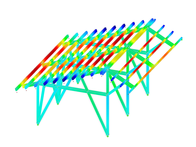
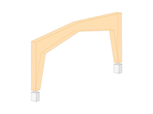
- Design of the following beam types:
- Parallel beam
- Monopitch roof beam
- Double tapered beam
- Arched beam
- Pitched cambered beam with constant height
- Pitched cambered beam with variable height
- Fish Beam - Parabolic
- Fish beam - Linear with rounding in central area
- Unsymmetrical beams with and without cantilevers
- Arrangement of a loose ridge wedge
- Optional consideration of stiffening elements for transversal tension
- Two design types available for stiffening elements concerning transversal tension:
- Constructive if required
- Full absorption of tension stresses perpendicular to grain
- Calculation of required number of stiffening elements for transversal tension and graphical representation of the arrangement in the beam
- Simple geometry input with illustrative graphics
- Convenient generation of snow loads according to EN 1991-1-3 or DIN 1055:2005, Part 5
- Automatic determination of wind loads according to EN 1991-1-4 or DIN 1055:2005, Part 4
- User-defined load cases and load applications
- Automatic generation of all possible load combinations
- Connection to MS Excel and access via COM interface
- Material library for both standards
- For design according to EC 5 (EN 1995), the following National Annexes are available:
-
DIN EN 1995-1-1/NA:2013-08 (Germany)
-
NBN EN 1995-1-1/ANB:2012-07 (Belgium)
-
DK EN 1995-1-1/NA:2011-12 (Denmark)
-
SFS EN 1995-1-1/NA:2007-11 (Finland)
-
NF EN 1995-1-1/NA:2010-05 (France)
-
UNI EN 1995-1-1/NA:2010-09 (Italy)
-
NEN EN 1995-1-1/NB:2007-11 (Netherlands)
-
ÖNORM B 1995-1-1:2015-06 (Austria)
-
PN EN 1995-1-1/NA:2010-09 (Poland)
-
SS EN 1995-1-1 (Sweden)
-
STN EN 1995-1-1/NA:2008-12 (Slovakia)
-
SIST EN 1995-1-1/A101:2006-03 (Slovenia)
-
CSN EN 1995-1-1:2007-09 (Czech Republic)
-
BS EN 1995-1-1/NA:2009-10 (the United Kingdom)
-
- Extensive library of permanent loads
- Allocation of a structure to service class, and specification of service class categories
- Determination of design ratios, support forces, and deformations
- Info icon indicating successful or failed design
- Color reference scales in result tables
- Direct data export to MS Excel
- DXF interface for preparation production documents in CAD
- Program languages: English, German, Czech, Italian, Spanish, French, Portuguese, Polish, Chinese, Dutch, and Russian
- Verifiable printout report, including all required designs. Printout report available in many output languages; for example, English, German, French, Italian, Spanish, Russian, Czech, Polish, Portuguese, Chinese, and Dutch.
- Full integration in RFEM/RSTAB including import of all relevant information and internal forces
- Design of members and continuous members for tension, compression, bending, shear, and combined internal forces
- Stability analysis for lateral-torsional buckling and buckling according to the equivalent member method or the second order analysis
- Serviceability limit state design by limitation of deflections
- Brazilian material library and cross-section library
- User-defined entry of rectangular and circular cross-sections
- Cross-section optimization with optional transfer to RFEM/RSTAB
- Optional import of effective lengths from the RSBUCK or RF‑STABILITY add‑on module
- Detailed result documentation including references to design equations of the used standard
- Various filter and sorting options of results including result lists by member, cross-sections, x-location, or by load case, load and result combination
- Consideration of moisture service conditions
- Visualization of the design criterion on the RFEM/RSTAB model
- Data export to MS Excel
You can create various load cases with a single mouse click. After the generation, the numbers of created load cases and result combinations are displayed.
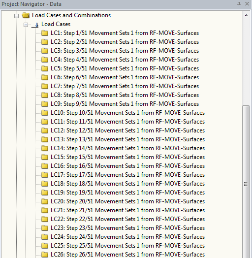
The RF-MOVE Surfaces add-on module does not have any result windows. You can check the created load cases including loads in RFEM.
Descriptions of the individual moving loads are created on the basis of the respective load step number. However, it is possible to edit the descriptions in RFEM.
You can export all data in tables to MS Excel.